Multi-Port Pulse Descriptor Word Interleaving on a Real-Time Control Loop
Testing an electronic warfare (EW) receiver requires a signal generation system which can emulate a range of scenarios from very simple pulsed RF signals to highly complex scenarios emulating densely populated RF environments. To accomplish this wide range of testing requirements, a test signal generator must comply with the specifications of the receiver under test. For example, frequency range, instantaneous bandwidth, and spur-free dynamic range must be considered by the test designer. A thorough discussion on the signal generator RF architectural tradeoffs can be found in [1]. On the back end of the test system, there must be a digital stream of data into the signal generator emulating the test environment. This digital stream of data is often a stream of pulse descriptor words (PDWs), which fully describe the characteristics of every RF pulse which the generator must produce.
The digital back end of the test system must properly convert the expected RF signal environment into a stream of pulse descriptor words (PDWs), which the signal generator can then convert to a real RF signal. The contents of a PDW consist of a timestamp, power level, modulation type, RF frequency, phase offset, and pulse width. Some signal generators allow additional parameters to be packaged into a PDW such as rise/fall time. The digital back end must be locked in time to the RF front end such that the timestamp of each PDW is accurate to a universal clock.
System Overview
This project will create a real-time stream of PDWs to multiple PDW interfaces using a single threaded CPU timing loop. The processor will consistently read a user-defined list of emitter-based signal descriptions and will create a real-time pulse stream out of a TCP/IP connection. Multiple PDW streams can be spawned for multiple independent, time-locked PDW interfaces such that simultaneous pulses can be generated across multiple generator ports.
The following block diagram describes the setup. In this case, a Rohde & Schwarz SMW200A signal generator was utilized as the digital-to-RF source capable of converting PDWs to real RF pulses.
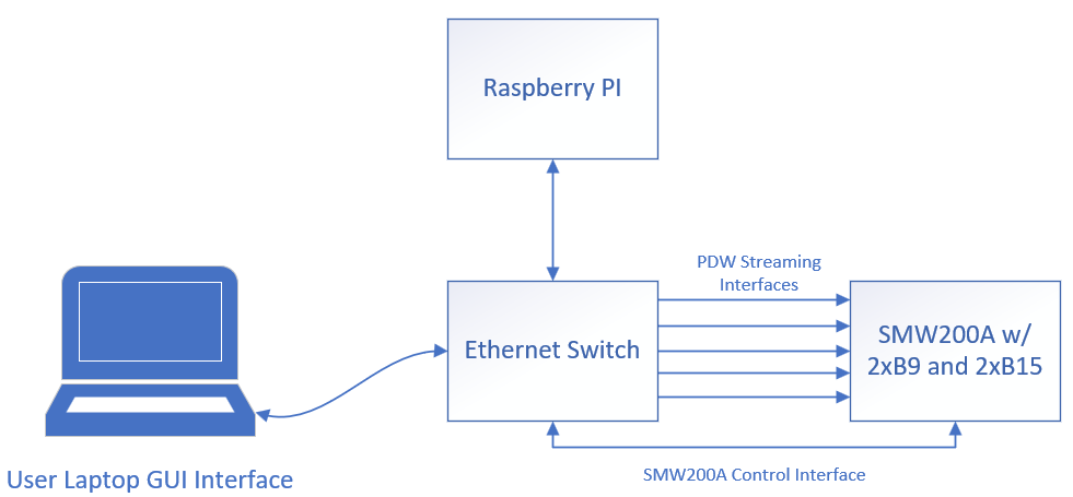
The Linux PC shown in the diagram provides a semi-real-time control loop for generating PDWs. The user laptop provides a user interface for configuring the signal generator and sending waveform descriptor words (WDWs) to the Linux PC running the control loop. The UI allows the user to specify a pulsed signal with a particular pulse width, pulse repetition interval, frequency, level, phase offset, and modulation type. Upon communicating WDWs to the Linux PC, the real-time control loop processes the WDWs and generates PDWs for the next 1 millisecond time interval. Every 1 millisecond, the loop restarts and processes the current list of WDWs. At the end of each cycle, the Linux PC sends the generated PDWs to the signal generator for the next 1 millisecond.
Software Architecture
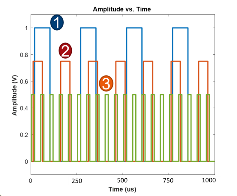
The software on the Linux PC is a compiled C program which continually reads a prioritized list of WDWs and generates the corresponding PDWs needed to create the desired waveform set. It is important to point out that the list of WDWs is prioritized. The highest priority WDW will ensure the generation of all PDWs associated with the WDW. Lower priority WDWs will have PDWs interleaved into periods of time when higher priority WDWs are not active, i.e. during pulse off times. The software can also interleave multiple waveforms on multiple independent PDW streams. For example, if a user has access to two signal generator PDW streaming interfaces, the control loop software is capable of interleaving completely independent WDW lists on both interfaces.
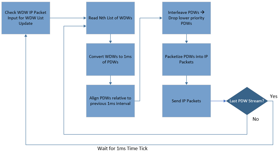
The C program begins by opening socket connections on all specified PDW interfaces. After initial configuration, the control process begins to operate in accordance with the above flow diagram. The loop checks if a user has sent a new set of WDWs to its input socket every 1 millisecond. If a new set of WDWs (assigned to a particular PDW interface) is present at the input buffer, the list is processed into the Nth WDW list as specified by the user. The software then takes each WDW in the first list and converts it to a set of PDWs covering 1ms of time.
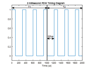
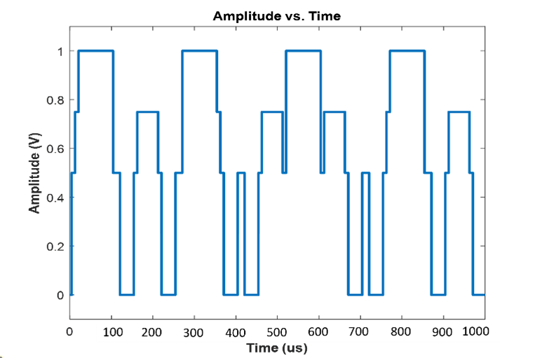
The software also tracks continuity relative to the previous 1ms time interval and applies the necessary timing offsets to each PDW. For example, consider a WDW describing a waveform with a 300us pulse repetition interval (PRI) and a 100us pulse width (PW). In the first 1ms timing loop, the software generates a PDW at 0us, 300us, 600us, and 900us. In the second timing loop the software must apply a 200us offset to compensate for the last PDW at 900us and the 300us PRI. Therefore, in the second timing loop, the software will generate PDWs at 200us, 500us, and 800us relative to the start of the second time interval.
PDWs are generated for a full 1ms for every WDW in the list. In the next step, the software takes each PDW array generated from the previous step and decides if any lower priority PDWs overlap in time with higher priority PDWs. If an overlap occurs, the lower priority PDW is negated from the PDW array. The output of this step produces a single PDW array containing interleaved PDWs from every WDW in the list. The array of PDWs is then packetized into PDW IP packets which follow the R&S SMW200A Interface Control Document (ICD).
The IP packets are then transmitted on the open TCP socket connected to the signal generator. If there is a second (or Nth) signal generator PDW stream, the software restarts the process of reading the WDW list associated with the Nth PDW stream. The WDW list is processed into a PDW stream and transmitted to the signal generator as described above. If the final PDW stream has been transmitted to the generator, the software will wait until the end of the 1ms time interval. Upon the start of the next 1ms time interval the software will check if the user has sent a new set of WDWs associated with any, or multiple, of the N interfaces. If there is new data in the buffer, the software will update the Nth WDW list and restart the process for the next 1ms interval.
On the user interface side of the system, the user will create lists of WDWs assigned to specific PDW interfaces. The user can specify parameters such as the PW, PRI, frequency offset, level offset, phase offset, modulation type, and pulse rise/fall time. The user can also configure the system to send the same set of WDWs out of all PDW interfaces with specified phase/frequency offsets. This configuration would provide angle of arrival capabilities in a direct inject multi-port receiver test.
User Interface
The user interface was written in the MATLAB application design suite. Prior to opening the UI, it is important to initiate the compiled C program executable on the Linux PC. Upon opening the UI, the user needs to begin by establishing the IP socket connection to the input socket on the Linux PC. Once establishing the input socket connection, the user can begin adding WDWs to the list and sending them to the Linux PC for execution on different PDW interfaces in the system.
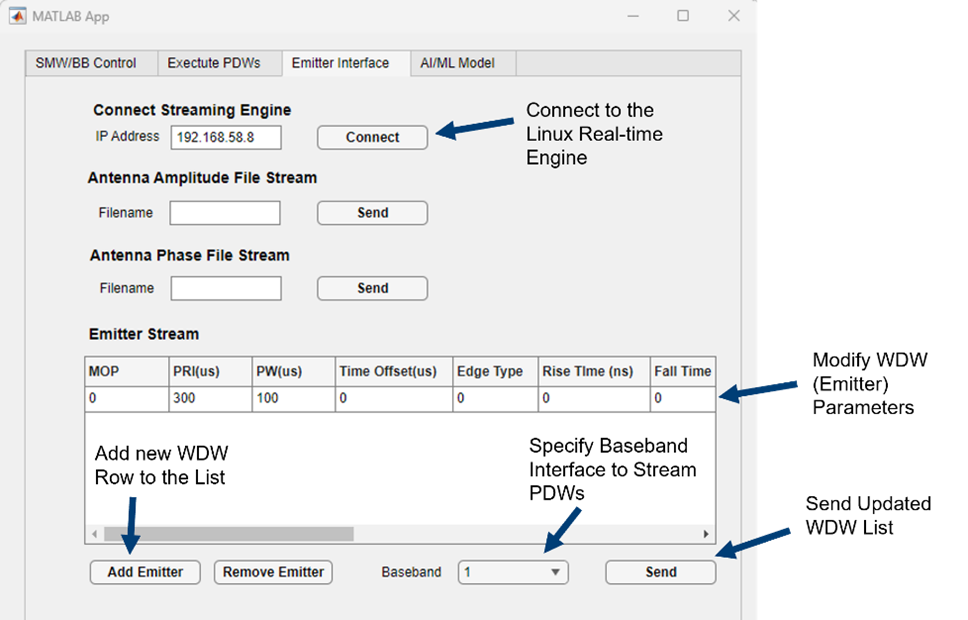
WDWs can be added to the list by selecting the Add Emitter button and specifying the waveform parameters in the WDW row. All parameters associated with a WDW can be specified in the table. The order of the WDW in the table specifies its priority on the associated PDW interface. Selecting the associated PDW interface can be specified in the baseband dropdown list. Once the list of WDWs is added to the table and the associated baseband is specified, the user can select the Send button to send the WDW list to the Linux PC. The Linux PC then processes the updated list.
Conclusion
The PDW test setup described in this discussion provides the user with a system capable of creating prioritized waveforms on multiple RF ports. The system presents a user interface that can easily create pulsed RF emitters in real-time without needing to specify PDW tables – a common occurrence in the EW test market. Furthermore, the interface enables plane wave emulation by presenting identical waveforms on multiple RF ports with specified amplitude, phase, and timing offsets. Although this interface does not provide a platform to create moving emitters, one could envision a similar architecture to enable such a system. Future enhancements to the software could realize this capability. Higher-level processing could be utilized to create moving scenarios with real-time feedback for hardware-in-the-loop test systems.