AI/ML Real-Time Signal Classification Using Rohde & Schwarz FSW and a Custom FPGA Design
Developing unique capabilities in the Aerospace and Defense RF industry requires high-performance downconverters and upconverters to cover extensive frequency ranges. By utilizing an up/downconverter over a wide frequency range, interesting capabilities can be developed on the digital backend of the system. Applications as fundamental as RF signal demodulation to more complex signal classification techniques can be explored.
The Rohde & Schwarz FSW signal analyzer can be used as a general-purpose piece of test and measurement equipment and as an RF-to-baseband IQ downconverter. Up to 1GHz of RF signal bandwidth can be downconverted and streamed over an optical baseband connection to an external FPGA interface. The FSW signal analyzer can be tuned anywhere in the RF spectrum from 2Hz to 85GHz. Additionally, the Rohde & Schwarz SMW200A signal generator can accept an input IQ stream with up to 1GHz of signal bandwidth. The input IQ stream can be upconverted to RF frequencies between 10kHz and 67GHz.
A Xilinx Alveo U200 Accelerator card was utilized in this project to create a platform for the implementation of unique applications in an external FPGA. The project showcases a fundamental AI/ML implementation of signal classifier application from a real-time IQ stream.
System Overview
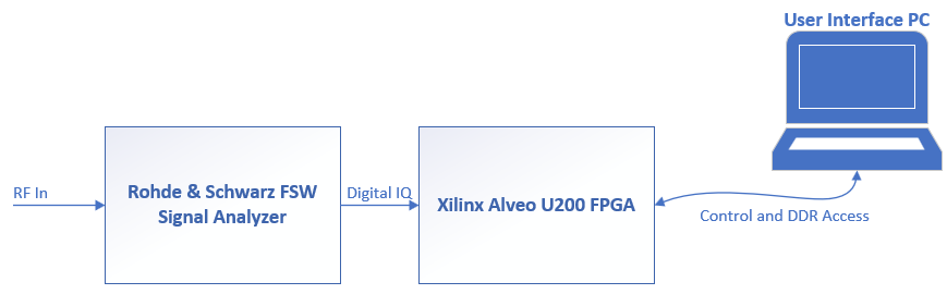
A Rohde & Schwarz FSW Signal Analyzer is utilized as a front-end downconverter to stream baseband IQ data into the external FPGA. The FPGA processes the IQ stream and outputs classification results to an external PC user interface in real-time.
The FPGA design requires three main block IP core implementations: an input IQ stream core, a data preprocessor core, and a MATLAB Deep Learning core. The input IQ stream core provides the connection mechanism to the Rohde & Schwarz FSW Signal Analyzer. This block interacts with the FPGA QSFP input transceiver connected to the FPGA IO pins. A 40 gigabit-per-second QSFP connection is established between the FSW digital output card and the FPGA input QSFP transceiver port.
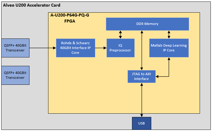
The data preprocessor block provides a conditioning mechanism to convert the input IQ data to the format required by the Deep Learning Processor (DLP) core. The FSW Signal Analyzer transmits data in 16-bit signed 2’s complement in-phase and quadrature pairs. Conversely, the MATLAB DLP reads data in 32-bit single value format specified by the IEEE 754 standard. In this implementation, the DLP is designed to process 2-by-1024-sample images. The DLP is a generic processor designed to process NxN images, which could be applied to numerous applications. In this application, the DLP processes RF input baseband IQ data which is transformed into 2-by-1024 images: 1-by-1024 in-phase and 1-by-1024 quadrature samples. The DLP processes data through a 28-layer convolutional neural network (CNN). The weights of the CNN are loaded into DDR memory through the user interface, which will be discussed in the following section.
Training and Deployment
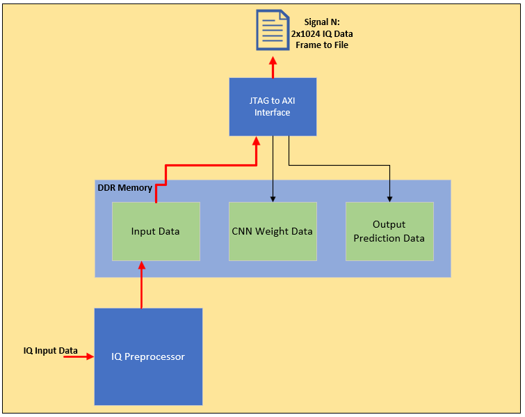
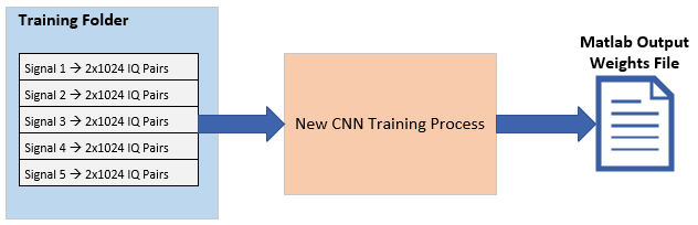
The CNN is pre-trained in an offline environment with multiple labelled signals in MATLAB. To train the network, a set of training images are formatted into independent MATLAB files containing 2-by-1024 samples. Each image is referred to as a frame. To collect the training frames, an initial set of IQ frames are captured from the FPGA design. The IQ streaming interface is initiated and an RF signal is fed into the front end of the FSW. The data from the IQ stream is then pulled from DDR into the external PC running the MATLAB application. The PC formats the input data into a set of files. Each file also contains a signal label associated with the signal of interest.
After the training set is collected, the user executes a MATLAB script to train a new 28-layer CNN with the training frames and their associated signal labels. Training time is highly dependent on the number of collected frames. A large training set could contain many variations of the same signal with multiple types of impairments applied to the input signal. A series of MATLAB toolboxes are required including the MATLAB Deep Learning Toolbox. The script produces a MATLAB file which provides a series of address-value pairs to load into the FPGA design in a specified DDR memory location.
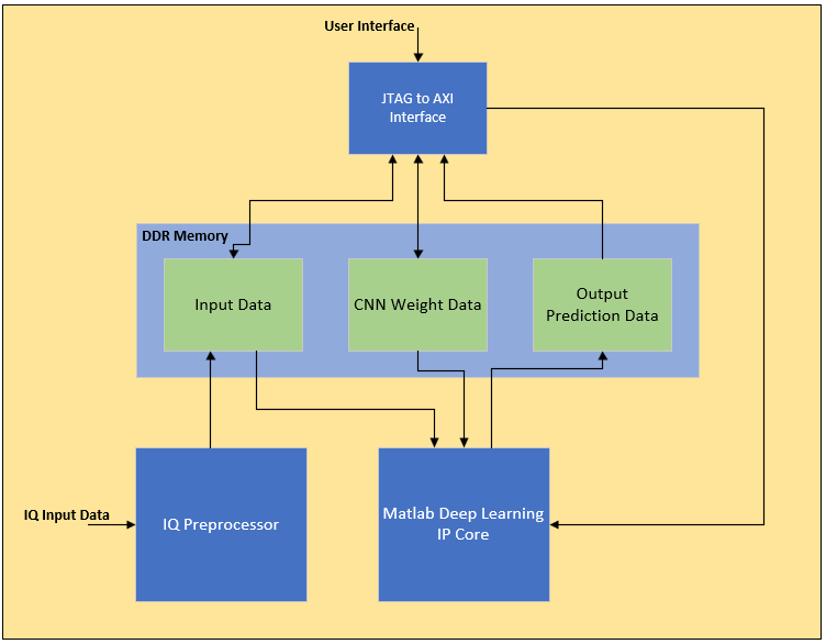
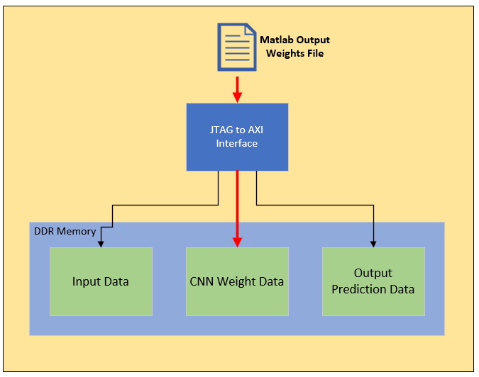
CNN Training weights are loaded over a low speed JTAG connection upon initial design boot-up. The IQ stream connection is initiated after loading the CNN weights. Data flows from the input IQ stream into a specified location in DDR memory. The DLP then pulls the frame from DDR memory to process the image through the CNN. An output prediction is then sent to a separate location in DDR from which the user interface can query the prediction.
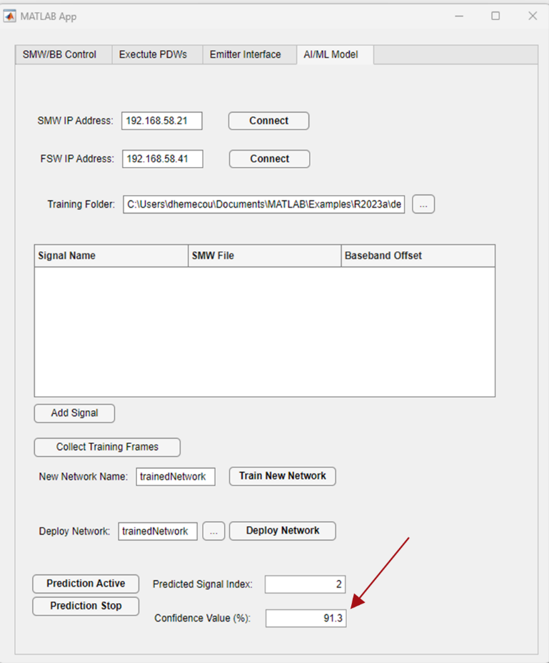
A custom user interface was designed in MATLAB to improve the ease of use for the classification. The user interface provides a mechanism to specify training signals, train the network, deploy the training weights, and to activate continuous polling of the FPGA to report the current prediction. For this test, the RF signals were designed and generated using a Rohde & Schwarz SMW200A Vector Signal Generator. Each waveform was created within the Rohde & Schwarz software suite for generating arbitrary waveform files. Within the user interface, the user can specify arbitrary waveform files to train the CNN. Each additional waveform file adds to the list of output signals the DLP can predict.
Signal Set Discussion
In designing the test setup, the concept of sample rate and signal image depth become an important aspect to consider. For the purposes of this demonstration, five independent signals are generated and trained on the network. The signals were chosen with specific parameters in mind to optimize the performance of the prediction. As discussed in the above sections, the signals fed into the system are converted to 2x1024-sample frames containing 1024 I and Q pairs.
Each frame is a real representation of a baseband signal downconverted from its RF frequency. Therefore, the center frequency of the original signal is not relevant to this specific discussion. The relevant piece of information is the sample rate of the baseband signal. The CNN is looking for patterns within the 1024-sample frame to uniquely classify a signal of interest based on pre-trained labelled signals. It is important that the signals fed into the system contain a set of unique IQ patterns within the 1024-sample frame. The unique nature of each signal frame improves the CNN’s ability to discriminate between signals.
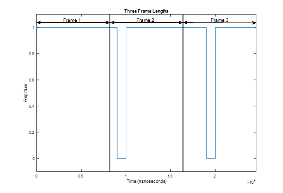
For the purposes of this demonstration, three pulsed signals, one continuous wave signal, and one QPSK communication signal are generated. In specifying the pulsed signals, the pulse width (PW) and the pulse repetition interval (PRI) needed to be properly designed such that the pulse on and off instances are captured within each frame. The minimum sample rate of the FSW Signal Analyzer streaming interface is 100.1MHz. For the demonstration, the sample rate is set to 125MHz, which corresponds to one sample every 8 nanoseconds. With a 1024-sample frame, the frame depth is 8.192 microseconds. It is desirable to provide pulsed signals with PWs and PRIs that exhibit at least one or two on/off cycles within the 8.192 microsecond frame.
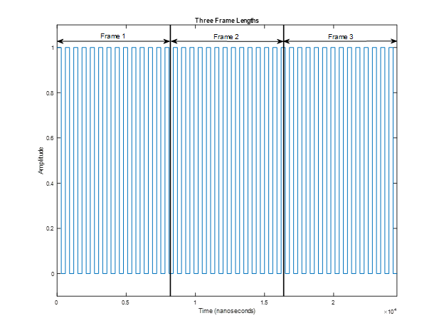
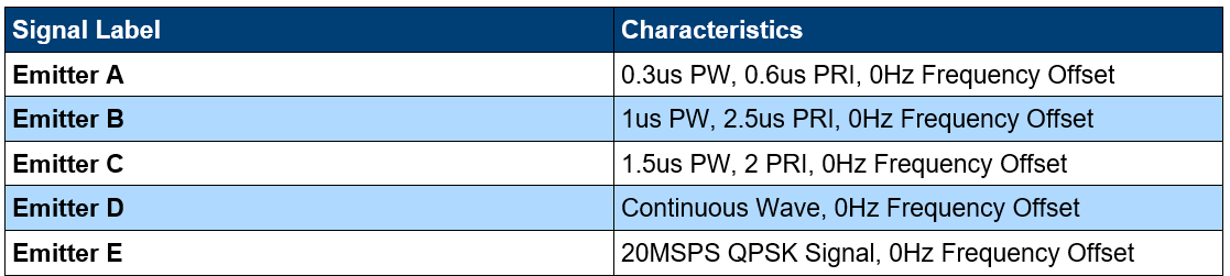
If the PW and PRI are too long, each frame can begin to look like a continuous wave signal or a non-existent signal. Conversely, if the PW and PRI are too low - i.e. lower than the sample rate - signal aliasing issues can begin to arise. Therefore, the three pulsed signals were chosen such that at least three cycles were generated within each frame to provide the CNN with unique and repeatable patterns. The following table describes the set of signals utilized in this demonstration.
This concept begs the question of how could one improve the architecture such that the CNN can classify a much wider set of pulsed signals? The answer lies in preprocessing. Preprocessing the input IQ stream into a set of parameters that extract more information from each signal is essential to improving the prediction and to reducing the DDR memory depth required for longer PRI and wider PW signals. Simultaneously, the introduction of preprocessing the data comes at the cost of added latency. For example, preprocessing a series of input IQ frames into a frequency and time domain image through a fast fourier transform (FFT) provides an improvement in the distinct features provided to the CNN. On the downside, feeding input IQ frames through an FFT-to-spectrogram preprocessor increases the latency from signal input to prediction output. Future improvements with a more robust preprocessing block could enhance the set of classifiable signals in the demonstration.
A possible solution to these architectural tradeoffs could be to feed the signal through two or more paths. Some paths may act on short IQ input frames, while other paths may act on deeper frames, while others may act on spectrogram-processed images. Additionally, a power level trigger could be implemented to begin processing data when a signal surpasses a certain power level – i.e. processing images only when a pulse rising edge is captured. This multi-path approach could provide a solution to a broader set of signals while maintaining the speed of a pure IQ-based approach.
Conclusion
This project displays a real-time AI/ML signal classifier derived from the use of a general-purpose signal analyzer as an RF-to-baseband downconverter. Utilizing high-end test and measurement equipment as both general-purpose test equipment and as a platform testbed for custom back-end FPGA applications can enable a more dynamic test suite. The AI/ML implementation displayed in this project provides an example of a system testbed application which could be improved by implementing some of the enhancements described in the previous section. Nevertheless, platforms like these open the door to a wide range of FPGA hardware-in-the-loop tests for custom designs.