Rohde & Schwarz SMW200A Agile Descriptor Word Streaming with Raspberry Pi
Source Code
Please find the source code for this project at the following GitHub URL:
https://github.com/ddhemecourt/SMW_ADW_StreamingAlso please note that the Raspberry Pi will require the Pi GPIO library, which can be found at the following link:
Pi GPIOIntroduction
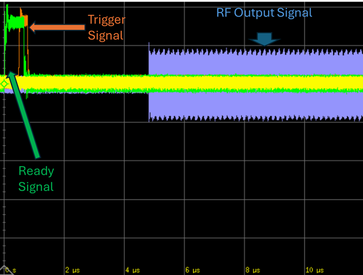
The R&S SMW200A provides multiple real-time interfaces for hardware-in-the-loop test systems. In particular, the K506 Agile Descriptor Word Streaming option provides an interface for streaming packets to the baseband of the SMW that specify an arbitrary waveform to activate. The K506 streaming interface allows the user to pre-load a table of arbitrary waveforms into the SMW200A baseband. Each waveform is provided an index which the user can reference in the streamed input Agile Descriptor Word (ADW). The interface can be activated in two different modes: infinite mode and deterministic mode. Instant mode immediately processes the input ADWs as they arrive at the UDP interface input to the SMW200A baseband. Deterministic mode provides a discrete hardware trigger input, which activates the input ADW upon the rising edge of the input trigger. The output RF waveform referenced in the ADW will become active within 6 microseconds of the input trigger being issued.
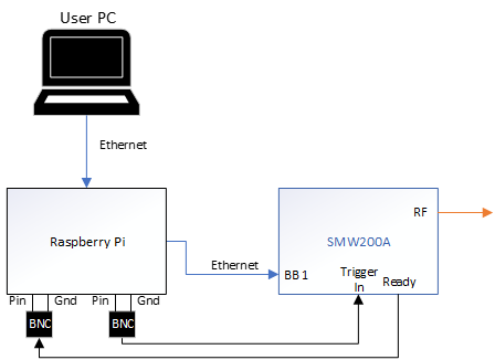
In this project, a Raspberry Pi model 4 is utilized as an input streaming source to the K506 ADW interface in deterministic mode. The Pi’s ethernet NIC provides the UDP packet input to the interface, while one of the signals on the 40-pin header provides the input discrete trigger.
Software Architecture
The Raspberry Pi hosts a C program which utilizes a configurable timing loop to send updated ADWs to the SMW200A baseband. The software consists of a simple cyclic task which looks for new ADWs provided by the User PC. Once a new ADW is present at the controller’s input, it sends the ADW and waits for the SMW200A to supply an active Ready signal. Once the controller reads an active Ready signal, it toggles an active high signal on its trigger pin to initiate the arbitrary waveform file specified by the ADW.
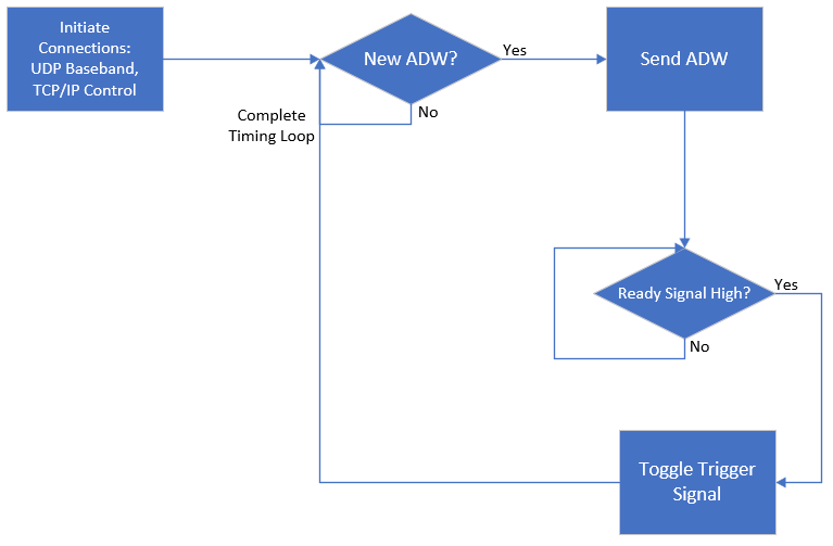
Note that if the ready signal does not become active within the timing loop, there is an error in the communication to the SMW200A. At this point the program will terminate.
Physical Hardware Setup
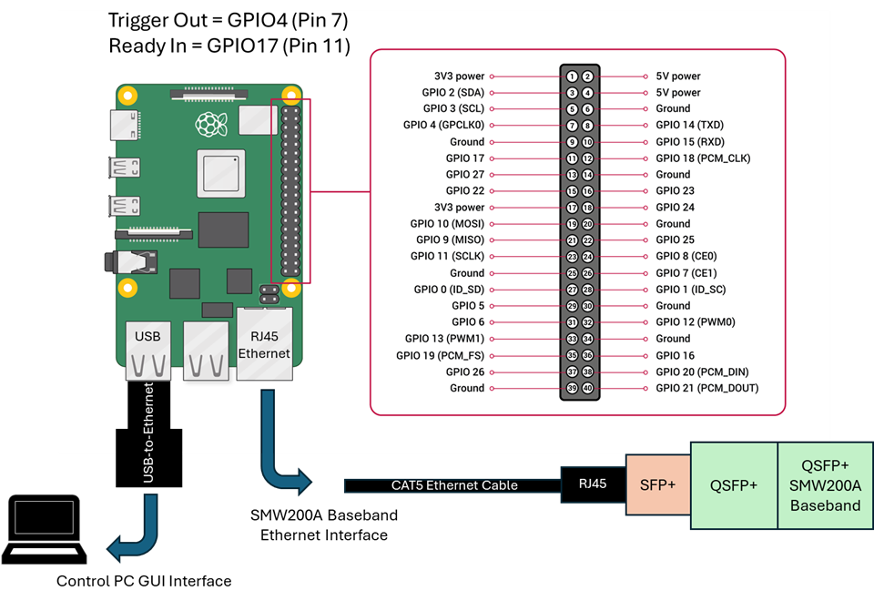
The physical hardware setup can be found in Figure 4. The Pi only comes with one dedicated RJ45 Ethernet interface. This interface is utilized to connect to the SMW200A K506 UDP Baseband interface. As it can be seen in Figure 4, the SMW200A interface accepts a QSFP+ connector. To access this connection from the Pi, the RJ45 interface needs to be adapted to the QSFP+ interface through the series of adapters depicted at the bottom of Figure 4. It is highly recommended to directly connect the K506 streaming UDP interface to the SMW200A. This helps avoid dropouts and latency of the UDP packets arriving at the SMW200A. Therefore, it is necessary to provide a separate Ethernet NIC to the Pi to connect to the external PC user interface. A USB-to-ethernet adapter can be used to accomplish this task.
Additionally, note that Pin 7 and Pin 11 of the 40-pin header on the Pi must be connected to two separate BNC connectors. These connectors are used to accept the SMW200A ready signal, and to drive the SMW200A trigger signal. The connector attached to Pin 7 must be connected to the SMW200A User 3 BNC interface. The connector attached to Pin 11 must be connected to the SMW200A User 1 BNC interface.
Configuring the SMW200A
The SMW200A must be configured to activate the K506 Agile Sequencer. To do so, select the baseband block in the front panel display and then select “Extended Sequencing”. Within the Extended Sequencing menu, select “Agile Sequencing” from the Mode dropdown list. Additionally, select the “Deterministic” option from the Operation Mode dropdown list.
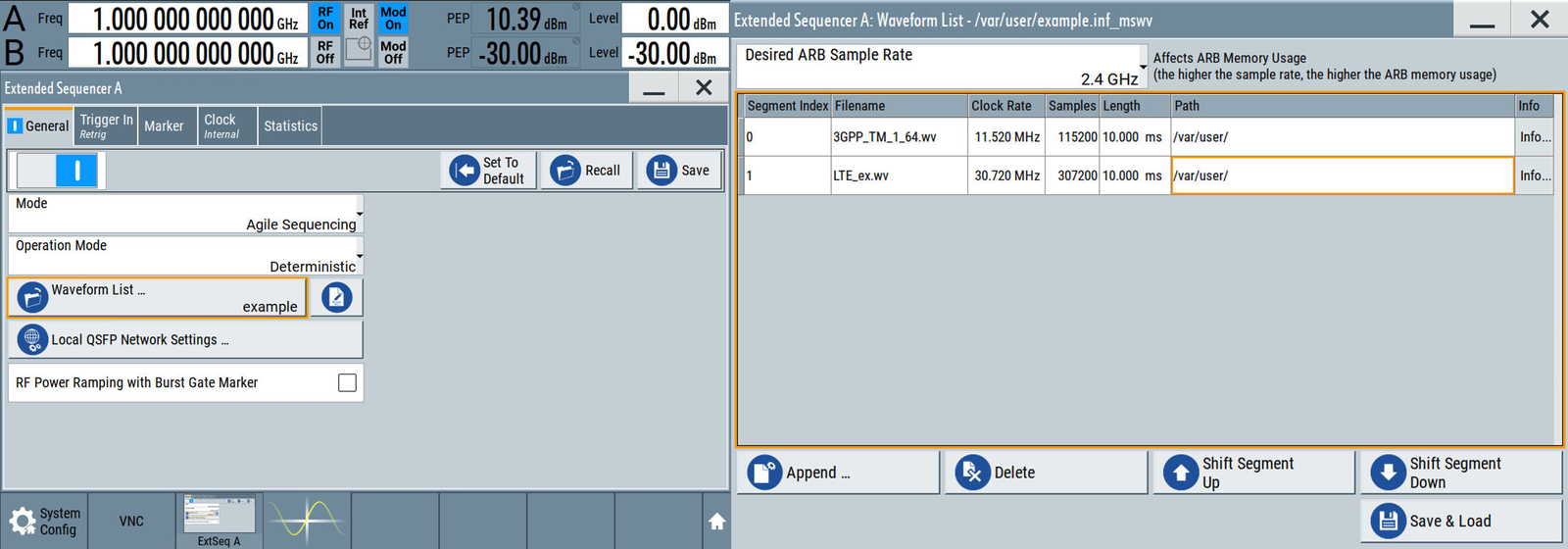
Below this option, there is a button to select the Waveform List. The user can create a new waveform list by selecting the “New” button or by recalling an existing list. Once the list has been recalled or created, the user can edit the list by selecting the edit icon next to the “Waveform List” button. A new window will pop up showing the waveform list. Within this window, the user can append or delete specific waveform files which the user can then call from the input ADW stream.
Additionally, within this window the user can specify the desired arbitrary waveform sampling rate. The sample rate needs to be consistent across all waveforms within the list. Therefore, every waveform must be resampled to the same sample rate with the dedicated sample rate selected by the user. The SMW200A will perform the resampling for the user. Higher sample rates provide access to wider bandwidth signals, with the tradeoff of high memory usage. It is important to note that the maximum memory usage (at the time of this writing) is 2GSamples of ARB memory depth. Once the Save & Load button has been selected, the SMW200A will resample the input waveforms as needed, and will load them into the arbitrary waveform generator.
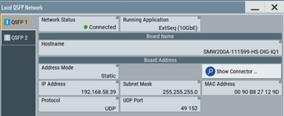
On the main Extended Sequencer screen, the user must also configure the QSFP network settings by selecting the Local “QSFP Network Settings” button. Within the pop-up window, the user can specify the network IP address. For this project, the Raspberry Pi controller requires the network settings as described in Figure 6.
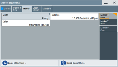
Finally, the SMW200A Ready signal sample width must be configured such that the Raspberry Pi controller has enough time to read the signal when it becomes active. To do so, the user must set the Duration field under the Marker tab to 10,000 samples.
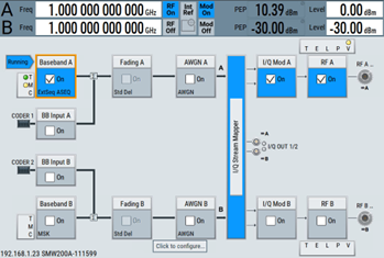
Once the above process is completed the SMW200A baseband is in a fully configured state to begin sending ADWs to the system. The user must also turn on the RF block and set the desired RF center frequency in the main SMW200A GUI.
User Interface
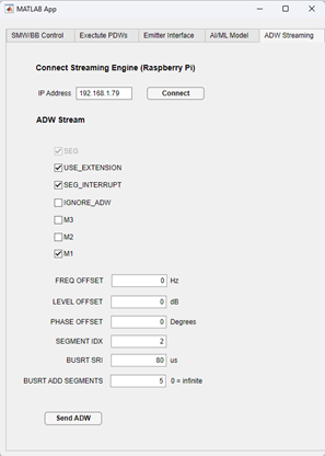
The user interface (UI) on the external control PC runs from a custom-designed MATLAB application. The application is made simple to send TCP/IP ethernet packets containing new ADW information to the Raspberry Pi controller. Figure 9 displays the UI where the user can specify the new ADW information to send to the controller.
To initiate the system, the user must open an SSH terminal to access the Raspberry Pi directory. The terminal can be accessed from any Windows-compliant SSH terminal software. MobaXterm provides a free software platform to access the terminal. The Raspberry Pi IP address defaults to 192.168.1.79. The user must log into the terminal using this IP address connected to the user PC. Once the user accesses the Pi’s directory from the MobaXterm terminal, the controller software must be initiated by calling the cyclic_RT_test executable with the following command:
>>> sudo ./Documents/ew_streaming/Linux_System_RT/cyclic_RT_test
The terminal will display a message that the server is listening for an input connection. At this point, the user can click the “Connect” button on the MATLAB application. The MobaXterm display will show an incrementing TIME value in the terminal. The user can now specify the parameters of the ADW to send in the MATLAB application. Once the parameters have been specified, the user can click the “Send” button to send the ADW to the controller. The controller will package the parameters into a properly formatted ADW, send the ADW to the SMW200A baseband, and issue the Trigger signal once the Ready signal is sensed as active. ADWs can be consistently updated as necessary.
Conclusion
The ADW streaming controller described in this discussion provides a seamless approach to demonstrating the deterministic mode of the SMW200A K506 Agile Sequencer. The project could be expanded to multiple SMW ports to provide simultaneous signals in a multi-port setup. Please see the video for the full system demonstration.
References
[1] SMW200A K506 Interface Control Document: K506 ICD
[2] SMW200A User Manual: SMW User Manual
[3] Source Code: https://github.com/ddhemecourt/SMW_ADW_Streaming
[4] Pi GPIO Library Install: Pi GPIO